Now that the initial trails setup is done, it’s time to get the audio effect in there. CHOPs in Houdini (channel operators) are really, really powerful, but they’re often the last part of the program that anyone touches. They can turn simple motion and effects into much, much more complex effects pretty easily. I still am unaware of the vast majority of things you can do with CHOPs, but I hope this example will be a good start for anyone who’s trying to learn Houdini…
Anyways. Starting from the geometry network we were in before, it’s time to make a chopnet manager. Double-click to jump into the channels context. Set one of your panes to “Motion View” if you don’t have it open already. Now lay down a file CHOP. You can import all kinds of information into a CHOP network, but in this case we’re going to use an audio file. Houdini seems to have trouble with some .MP3 files, so you might be better off using a .WAV file or converting an .MP3 to a .WAV. You can leave everything else at the default. If your music doesn’t start right at the beginning of the track, you can append a Shift CHOP and change the “Start” parameter to move the audio back a few seconds.
Another aside: to preview audio in Houdini, you need to click the little icon in the bottom-right corner that looks like a speaker, set the mode to “Scrub,” and point to a CHOP or a file you want to play while the timeline plays.
Now, if you hold middle-click on your File or Shift CHOP, you’ll likely see two audio channels: chan0 and chan1. Those are stereo channels. We don’t really need both of those channels, so append a Delete CHOP and delete chan1. It’ll save a little time later on when we need to do a few operations down the line.
Next up, we want to compute the amplitude of our audio. To do that, append an Envelope CHOP. You can mess around with the Envelope Width later on. It’s not a bad idea to resample the audio by checking “Resample Envelope” and setting your sample rate to something reasonably high, depending on your audio and whether your Common settings for the CHOP are in frames or seconds. Audio curves can get pretty dense depending on the original sample rate, and you really typically don’t need that level of fidelity. Again, this can be adjusted more later on.
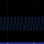
Now append a Trigger CHOP. The Trigger is meant to take channel data and turn it into distinct “attacks”: if you’re familiar with MIDI, you’ll know the “attack, sustain, decay, release” structure. What we’re looking for is for the value of this curve to be zero except when a “beat” is happening, in which case we want a very fast ramp-up to a value of 1.0 (the attack), a brief hold at 1.0 (the sustain), and a slightly slower tapering off back to zero (the decay/release). The “Trigger Threshold” parameter controls what amplitude is the minimum for activating the trigger. You’ll need to mess with this value the most to control when a beat happens. You’ll probably also need to adjust the Envelope Width and Sample Rate on the Envelope CHOP. Keep tweaking the sliders around on both the Envelope and Trigger CHOPs until you have a curve that looks something like the one in Fig. 1.
Next up, we’re going to take this trigger information and use it to blend between two other channels: a channel with a constant value of zero, and a generated noise channel. When I originally created this effect, I wanted to use the actual waveform of the audio to displace the motion trails, but the real waveform just didn’t look that good. Generated noise had the pattern I was looking for, and was a little easier to control, so that’s the setup we’re using here. You could use a real waveform if you wanted to in place of the generated noise, feel free to experiment.
Start by creating a Wave CHOP (in the same CHOP network, but not connected to the previous CHOPs). I used a Triangle type wave, but you can use whatever you think looks best. The Period of the wave is probably going to need to be very small unless your scene scale is huge, try starting with a value of 0.05. Everything else is relatively unimportant right now.
We’re going to mix up this waveform with a little noise. Create a Noise CHOP (don’t append it to the Wave CHOP). I used Sparse noise, but again play around with the types and see what you like. I set the Period to 0.005, and the Amplitude to 4.
We also need to make a channel that’s going to act as the blender between these other two channels. Create a Channel CHOP. Add just one channel, you can name it “blend” or whatever you want. The type should be float, and the size is 1. Set the value to 0.5 for now, you’ll be adjusting it later. Finally, we’re going to tie all three of these channels together with a Blend CHOP. The channel that drives the blend amount (using a range from 0 to 1, like a ramp) needs to be the first input, so connect your Channel CHOP to the Blend first. Then connect your Wave and Noise CHOPs to the Blend. Make sure to turn on “Omit First Weight Channel,” since we only want to use it as a blender, not as actual channel information.
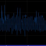
You should end up with a channel looking something like the one in Fig. 2. It’s a waveform that’s slightly blended with a noise pattern, enough to make it a little more visually interesting. You can control how much noise is in the curve by adjusting the “value0x” of the Channel CHOP you created from 0 (no noise) to 1 (entirely noise).
Next up, we need to extend this generated pattern so that it lasts as long as we need it to, so just append an Extend CHOP and set the Right Behavior to “Cycle.” The noise is irregular enough that nobody is likely to notice a repeating pattern in the motion trails.
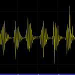
So now we have two separate channels… a trigger channel that goes from zero to one based on the amplitude of the music, and a waveform channel that generates the visible pattern we want. Now what we need to do is have the waveform channel scaled by this trigger channel, so that the waveform is only really visible when the trigger is activated. To do this, we’ll just multiply the channels together using a Math CHOP. Set the Combine CHOPs to “Multiply.” If your channels from the Trigger and the Extend CHOPs are named the same, you can set the Match By parameter to “Channel Name.” Otherwise, if you only have one channel in each of those nodes, “Channel Number” is fine. Under the Mult-Add tab, the other setting to play with is “Multiply,” which will multiply the result of the Math CHOP by a scalar. This is effectively the amplitude of your final curve. Your curve should look something like Fig. 3 here.
We’re almost done with the CHOP network. It’s good practice to name your channel something useful, so append a Rename CHOP and rename your channel from whatever it’s currently named (likely “chan0” or “chan1”) to “waveform.” Then append a Null CHOP. Nulls are great for exporting data, since you can easily see them in dropdown lists if you name them in capital letters, and you don’t have to worry about other connections to your network breaking later on if you need to append extra nodes to your network. Name the Null CHOP something like “CHOP_OUT.”
Now we have to jump back to the POP network you made earlier. Go inside the POP Network. We’re going to insert a few nodes between the Force POP and the Drag POP we made earlier. First, we need to define exactly which points we’re going to be moving for each frame. We don’t want to move the points that have just been emitted, since that would push the start of the trails away from the body, which would look weird. Instead, let’s make a group out of particles that have been alive just a little bit longer than that… say, three frames. Append a Group POP. Set the Group Name to “displaceGroup.” Under the Rule tab, check “Enable” and set the rule to $AGE == 3/$FPS. This means that the group will evaluate to include only particles whose were born exactly three frames ago ($AGE gives you the particle’s age in seconds, so we divide it by the $FPS variable to get frames).
Now to the good part– we’re actually going to take this group of particles and translate them based on the value of that CHOP network. Append a Position POP. This node lets us manually define the position of any particle. Set the Source Group to “displaceGroup.” For this example, we’re only going to modify the Y-coordinate of these points, since we’re looking at this animation from the side. If you have the inclination, you could move the points instead along the normal for each point, or use a VOP POP to handle the translation in VOPs, but I’ll stick to the slightly easier-to-understand Position POP. Leave the x and z position values to $TX and $TZ, which are the current coordinates of the particle. For the y position, input the following expression: $TY+chopf("../../chopnet1/CHOP_OUT/waveform",$FF)
This expression looks a bit ugly if you’re not used to using them, but it really isn’t that complex. We are taking the existing Y-coordinate of each particle, $TY, and adding the value of the channel we created in the CHOPnet at the current frame. The chopf() expression looks for the path to a CHOP channel, which, relative to our current path, is “../../chopnet1/CHOP_OUT/waveform”, and then wants a frame, which we set to the current frame as a floating-point value ($FF).
If you try playing the simulation now, you should see your particles being bumped around by the audio channels! Just a few more things to do before the effect is totally finished.
There will be situations where the particles get way too close to each other, especially when the emitter isn’t moving fast enough. To alleviate this problem somewhat, we can give the particles a sort of electrical charge, forcing them apart. To do this, append an Interact CHOP. Set the Particle Radius to “Use Supplied Radius” and the Effect Radius to “Use Supplied Radius.” The Particle Radius is the virtual radius of the particle, almost like a collision radius. The Effect Radius is a sort of padding around the particle, within which the particle’s electrical charge can be felt. You can set your own values for the two radii- I used 0.2 for the Particle Radius, and 0.5 for the Effect Radius. The settings will depend on your scene scale and motion. Under the Behavior tab, you can set your Force Multiplier to scale back the repulsion force a little bit, maybe to 0.3 in all directions. Finally, under the Defaults tab, check “Override Charge” and set the charge to 1. This means that all particles will have a positive charge, and since particles with similar charges repel (think magnets) the particles will push away from each other if they bunch up too close. The settings on this tab will have to be messed with a bit in order to get good results– settings that are too high will result in your trails exploding.
Try your simulation now! If the audio bumps are a little too big, try adjusting the final amplitude of your CHOP channel (the post-multiplier in your Math CHOP). If they happen too often or not often enough, check your Envelope CHOP. If they fall off too quickly or start too slow, adjust your Trigger CHOP.
There are a lot of settings to mess with, and it’s really annoying to have to jump all over your networks to adjust these things, so the next part of this tutorial will show you how to package this whole effect into a single node, with an interface that controls all these parameters in one place. You can then save that node to your own personal library and use it anywhere you like, or share it with other Houdini users. As always, if something doesn’t work right or if you have any questions, feel free to comment away.
